Technical Description
The Spheroconical Cam can be considered a development and an optimization of the Cylindrical cam.
In the pictures below the functioning principles of a Cylindrical (fig.1)and Spheroconical cam (fig.2) are schematically shown.
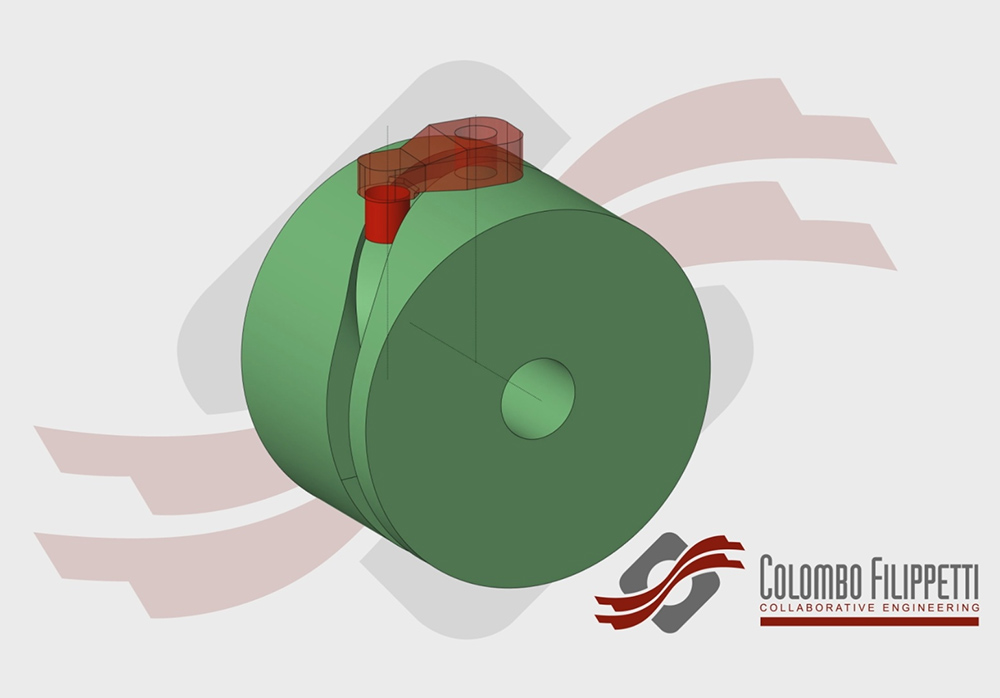
Fig. 1
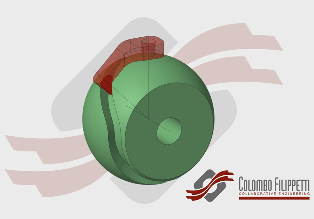
Fig. 2
The basic difference between a Spheroconical and Cylindrical Cam is in the orientation of the follower in the follower’s wheel (C). In the Cylindrical Cam the follower’s axis is parallel to the output rotation axis while in the Spheroconical Cam the follower’s rotation axis (C) will always pass through the intersection between the Cam rotation axis (B) and the output rotation axis (A)
In the Spheroconical cam, unlike the Cylindrical cam commonly used, the contact surface between the follower and the cam’s profile is constant, using the whole height of the follower. In the Cylindrical cam the height of the contact surface varies during the rotation.
For this reason the engineers must increase the diameter of the Cylindical cam to obtain a better contact, but the compactness and the speed of the machine is reduced.
The contact between the cam profile and the follower does not create any axial sliding movement so the friction is reduced and:
-▪ efficiency is increased
-▪ reliability is increased
-▪ lifetime is increased
-▪ operating speed is increased
-▪ maintenance is reduced
Typical application of the Spheroconical cam
The Spheroconical cam can be used to transfer objects between two transfer lines and to reorient them. The output follower’s wheel is dragged by the machine driver and rotates around the fixed Spheroconical cam, while the follower’s lever oscillates around its axes as imposed by the motion law of the cam profile. The dragging forces the follower’s wheel to meet the picking and posing positions and the cam profile rotates the object.
In the video below the Spheroconical cam is shown trasferring and reorienting sanitary napkins.
The Spheroconical cam can also be used to move the polishing heads for marble, granite and tiles.
Advantages
The usage of the Spheroconical cam allows the development of compact and faster systems with a better efficiency, due to the reduced friction in the followers.
Customization
With the Spheroconical cam a variable number of follower’s levers can be positioned around an external circumference. The maximum number of followers depends on their shape and dimensions.
The Spheroconical cam permits to configure the follower’s lever in a ‘forward’ or ‘backward’ position referred to the follower’s wheel axis. The follower’s lever rotates in the opposite direction of the ‘forward’ when configured as ‘backward’.
It is possible to orient a follower’s lever ‘forward’ and the next ‘backward’ to obtain the parts placed with opposite orientations while picked with the same orientation.
In the videos 1 and 2 the ‘only forward’ and ‘forward-backward’ configurations are shown.
The components used are the same, only the assembly is different.
Patent
INMAN S.r.l. is proprietary of the following patents regarding the Spheroconical cam:
International patent No. PCT/IB2013/000639
National Patent:
EUROPA, No. 13724865.4 -
USA, No. 14/783167 -
CINA, No. 201380075521.7